LCSMar Local-First
Liquid Cargo System Simulator — Technical Reference
Physics-based simulator for liquid cargo operations on oil and chemical tankers. Models inert gas atmosphere, cargo heating, crude oil washing, vapour generation, piping hydraulics, methanol dual-fuel operations, and intact stability & hull-girder strength in a unified real-time environment.
The pilot installation is configured document-true to a Reference MR Tanker — a ~50,000 DWT IMO II chemical/product carrier with methanol dual-fuel (LGIM) propulsion: twenty cargo tanks including a dedicated methanol storage pair served by deepwell pumps, a combustion-type inert gas generator, segregated ballast with treatment plant (filter + UV), and a daily methanol service tank feeding the main engine. Tank calibration tables, hydrostatics, cross-curves and the piping topology are all extracted from the vessel's class documentation; the ship herself stays anonymous here.
Designed as a digital twin for cargo operations training — the architecture prioritises ingestion of real operational documents (loadicator condition exports, sounding logs, gas readings) to anchor the physical engines against actual vessel behaviour.
The stability and strength chain is validated against the vessel's class-approved documents: the hydrostatic pipeline reproduces capacity-plan load-line points within 0.02 m and six worked conditions of the trim & intact stability booklet (KMT within 0.05 m); still-water shear force and bending moment reproduce the booklet curves via an inverse-calibrated buoyancy model (mean R² ≈ 0.99 across the LD02–LD23 envelope); loading conditions round-trip against real loadicator exports within instrument tolerance. LCSMar is a training simulator — it is not a class-approved loading instrument and does not replace the ship's loadicator.
Architecture
┌─────────────────────────────────────────────────────────┐
│                    React + TypeScript                    │
│  P&ID Renderer (SVG) │ Stability │ Calibration │ Tanks  │
├─────────────────────────────────────────────────────────┤
│              WebSocket (real-time frames)                │
├─────────────────────────────────────────────────────────┤
│                  FastAPI + Python 3.12                   │
│  Simulation Engine │ Flow Solver │ Calibration Solver    │
├─────────────────────────────────────────────────────────┤
│           Vessel Definition Spec (VDS / JSON)           │
├──────────────┬──────────────┬───────────────────────────┤
│  PostgreSQL  │    Redis     │  Calibration Store (JSON)  │
└──────────────┴──────────────┴───────────────────────────┘
Frontend — React 19, TypeScript, Zustand. SVG-based P&ID renderer driven by vessel definition geometry. Views: Cargo (P1/P2), Ballast (tanks/pump room), Inert Gas, Tank Cleaning, Methanol, Bunker/ER, Heating, Tanks, Stability.
Backend — FastAPI, Python 3.12. Eight physics subsystems run at fixed 0.5 s timesteps, accelerable to 16×. Newton-Raphson flow solver, lumped-parameter thermal model, exponential gas dilution. WebSocket pushes delta-compressed frames to the frontend.
Vessel Definition Spec — JSON schema defining hull geometry, tank calibration tables (ullage → volume → VCG → IT), piping networks, hydrostatic tables, cross-curve data, P&ID layout coordinates, and alarm thresholds. Vessel-agnostic: any tanker can be modelled by providing a VDS file.
Calibration Loop — Operators log observations (measured vs. predicted) via the UI or Excel upload. A statistical solver computes parameter adjustment suggestions from residual analysis, which the operator reviews and applies.
Installation
# Prerequisites: Docker, Docker Compose
docker compose up -d

# Frontend: http://localhost:3002
# API:      http://localhost:8002
# DB:       localhost:5437 (PostgreSQL 16)
Development
# Backend
cd backend && python -m venv .venv && source .venv/bin/activate
pip install -r requirements.txt
uvicorn main:app --reload --port 8001

# Frontend
cd frontend && npm install && npm run dev

# Tests
cd backend && pytest                          # 750+ tests
cd frontend && npm test                       # 42 tests
Tech Stack
| Layer | Technology |
|---|---|
| Frontend | React 19, TypeScript, Zustand, Recharts, Vite |
| Backend | Python 3.12, FastAPI, NumPy, SciPy, openpyxl |
| Infrastructure | PostgreSQL 16, Redis 7, Docker Compose |
| Testing | pytest (750+, incl. class-data validation oracles), vitest (42) |
Inert Gas Atmosphere
Models O2 and HC concentration decay in cargo tank ullage spaces during inerting, purging, and gas-freeing.
Dilution
Exponential decay assuming perfect mixing:
Pressure
Driven by IG inflow and liquid level change:
P/V Valve
Proportional relief (not binary). The valve modulates flow proportionally to pressure deviation from setpoint:
Flow Distribution
Total IG supply from running blowers splits equally among open tank isolation valves, after mast riser diversion (85% when open). Deck isolating valve gates all flow.
Piping Hydraulics
Steady-state Newton-Raphson network solver for multi-system piping (cargo, ballast, IG, tank cleaning run simultaneously with shared tank states).
Pipe Friction
Darcy-Weisbach with Churchill correlation (all Reynolds regimes):
Valve Loss
Cv method with equal-percentage characteristic:
Pump Head
Parabolic H-Q curve with affinity law speed scaling:
Convergence
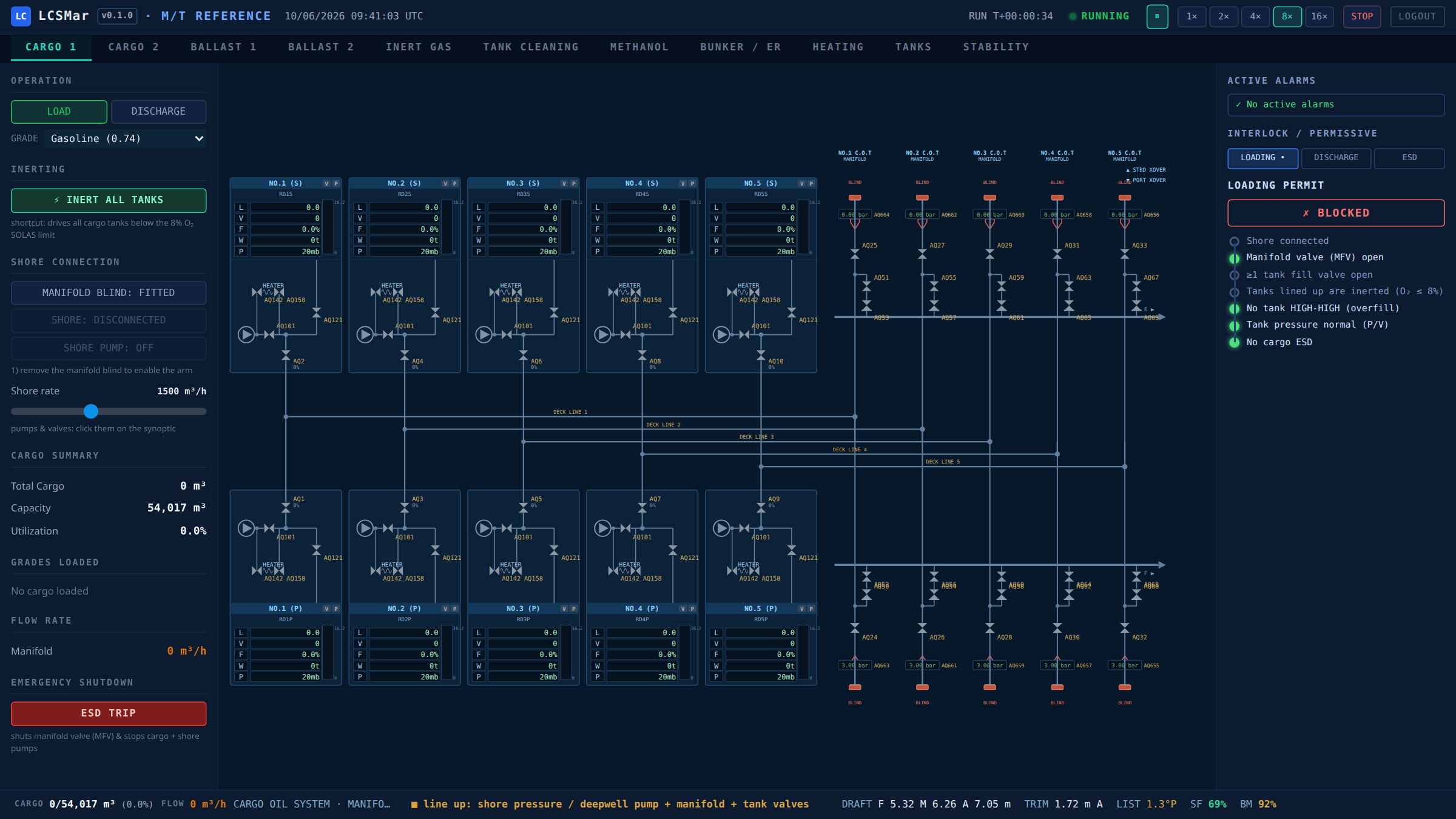
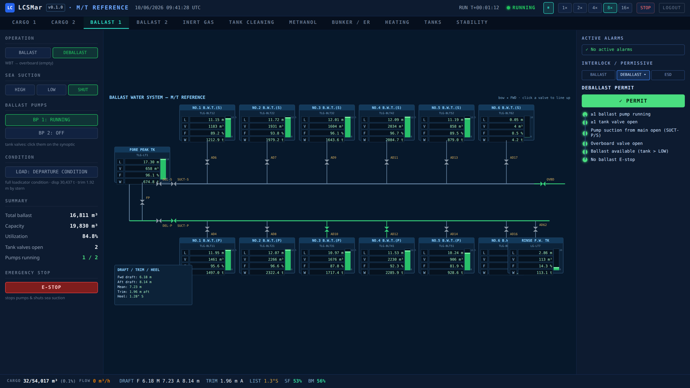
Damped Newton updates (α = 100/max(dx)), regularisation near zero flow, max 50 iterations, tolerance 1×10⁻⁶ m³/h. Check valves enforced via iterative re-solve blocking reverse flow; pump discharge non-return valves make line-up direction physically meaningful — deballasting must enter through the suction crossovers, exactly as on the real system. Inventory is conserved across tank-full and run-dry events to numerical precision.
Ballast pump room during a live deballast: tank → main → suction crossover → pump → treatment train → overboard, with the permissive panel granting the line-up.
Stability & Hydrostatics
Intact stability calculation from weight/moment summation and hydrostatic table interpolation.
- Displacement: Δ = mlightship + Σ(Vtank × ρcargo)
- Centre of gravity: KG = Σ(mi × KGi) / Δ, LCG and TCG likewise
- Draft: reverse-interpolated from hydrostatic table (draft → displacement)
- GM: GMsolid = KMT − KG; free surface correction FSE = Σ(ρ × IT / Δ) for slack tanks (2–98% fill); GMfluid = GMsolid − FSE
- Trim: trim = Δ × (LCG − LCB) / MCTC
- List: tan(θ) = TCG / GMfluid
- GZ curve: GZ(θ) = KN(θ) − KG × sin(θ), interpolated from cross-curve tables
IMO intact stability criteria (A.749) checked automatically: area under GZ curve to 30°/40°, maximum GZ, angle of maximum GZ, initial GM.
Hull-girder still-water shear force and bending moment are computed live from the same tank states, against the class allowable envelope. The buoyancy distribution is inverse-calibrated from the trim & stability booklet's own SF curves (no Bonjean data required), reproducing the booklet within a few percent across the operational envelope.
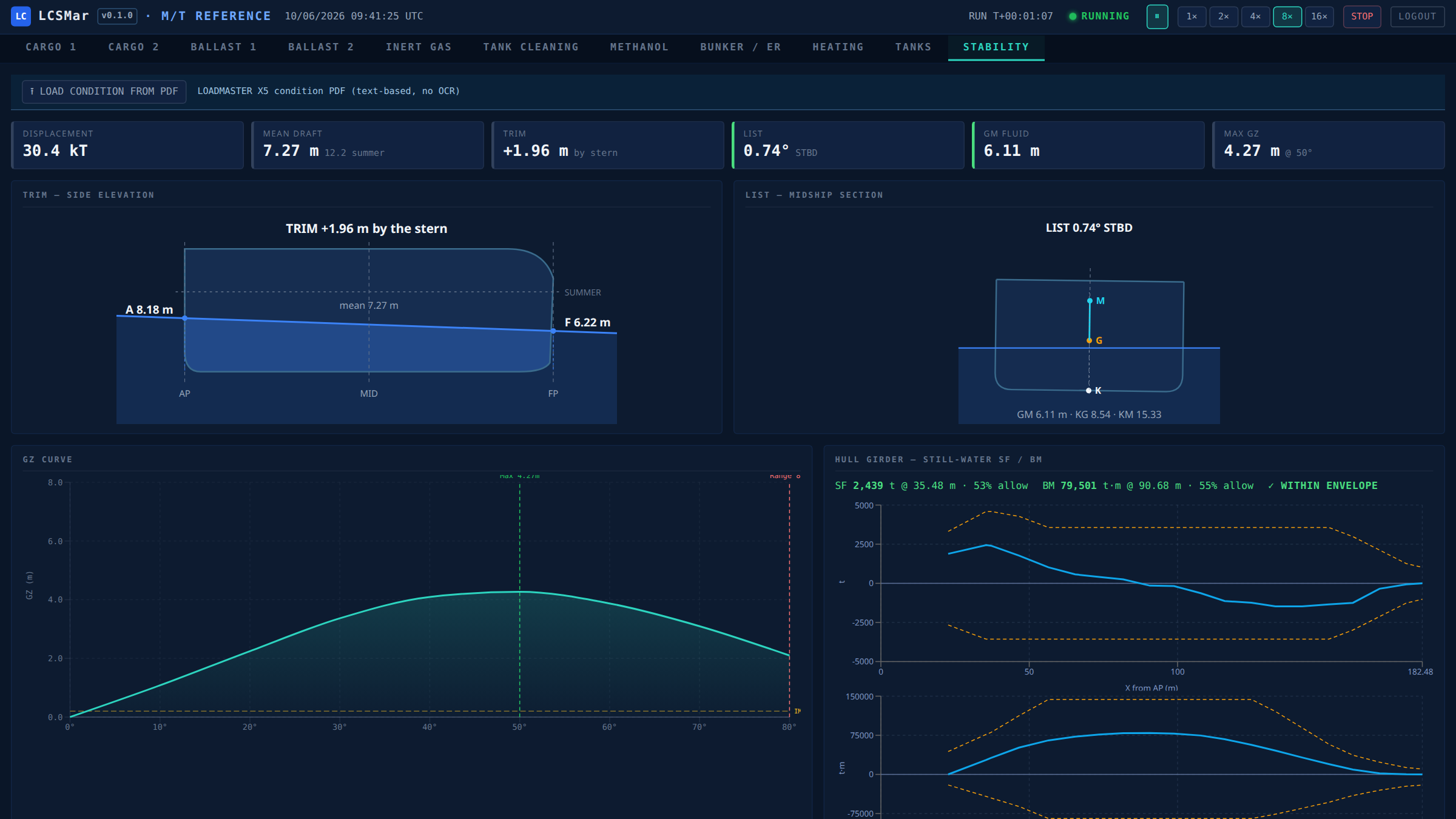
A full 77-tank departure condition loaded from a loadicator PDF export: drafts, GM, GZ curve and still-water SF/BM all within the class envelope.
Thermal Model
Lumped-parameter heat balance per tank:
\( Q_{\text{coil}} = U_{\text{coil}} \cdot A_{\text{coil}} \cdot (T_{\text{steam}} - T_{\text{cargo}}) \) — heating only
\( Q_{\text{loss}} = U_{\text{hull}} \cdot A_{\text{hull}} \cdot (T_{\text{cargo}} - T_{\text{ambient}}) \) — always active
Defaults: Ucoil = 50 W/(m²·K), Uhull = 5 W/(m²·K), steam at 170 °C, Cp = 2000 J/(kg·K). Coil and hull areas scale with tank volume. Alarms on flash point and pour point approach.
Crude Oil Washing
Surface coverage model:
Vapour Generation
VOC generation from cargo surface, proportional to Reid Vapour Pressure:
Methanol Operations
A dedicated trainer for methanol-as-fuel operations, built from the vessel's methanol safety-system cause-and-effect documentation and bunkering procedure: bunkering (shore/barge → manifold → storage), transfer (storage → deepwell pump → daily service tank) and normal running (service tank → supply unit → master fuel valve → main engine).
- Start-permissive chains rendered as live logic bars per operation — N&sub2; mode, tank inerting ≤5% O&sub2; via the main IG line, vapour-return connection, N&sub2; line pressure tests, level-alarm tests, valve line-up in procedure order, manifold last.
- ESD cause-and-effect matrix: gas detection ≥40% LEL in any zone, fire detection (engine surround / pump room), service-tank high-high, bilge leak, manual trip — each cause and every effect (supply shutdown, ESD valve closure, master fuel valve, second-fuel changeover, N&sub2; purge) tracked live.
- Mass-conserving hydraulics: transfers run through the real network solver — storage loss equals service gain to numerical precision, verified end-to-end in the test suite.
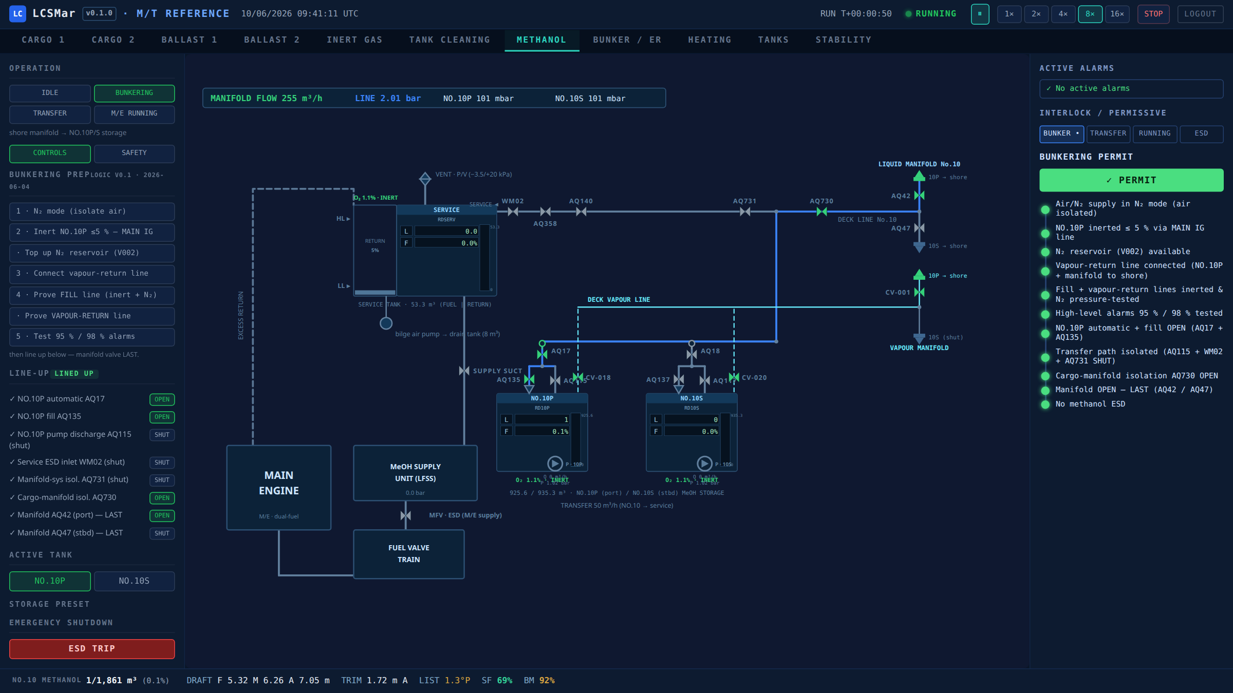
Methanol bunkering with the full permissive chain granted — manifold flow live, both storage tanks filling, vapour return to shore.
Loading Conditions
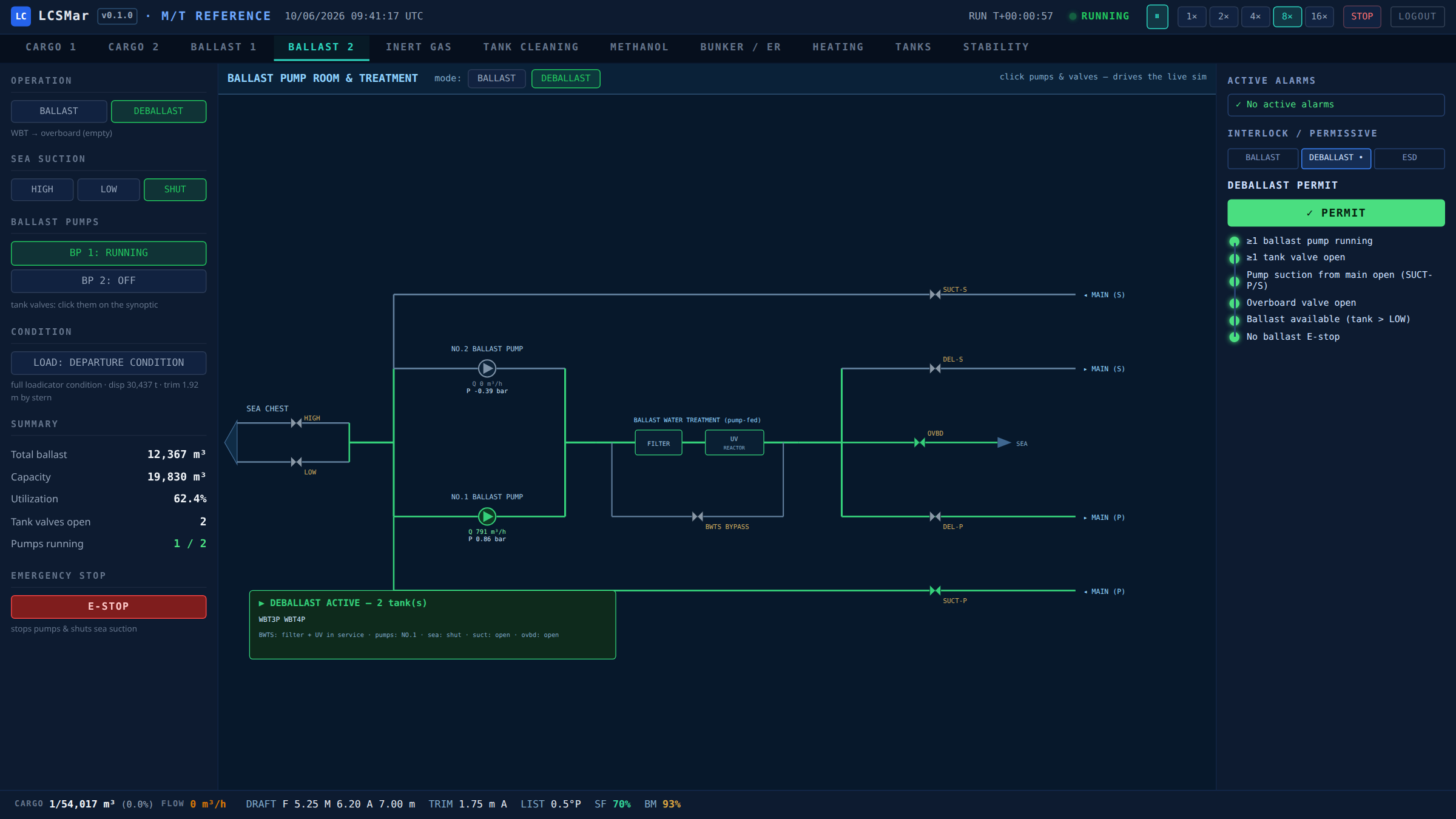
Real loadicator condition exports (text-based PDF) are parsed directly in the browser session — the PDF itself is never stored server-side. The parsed snapshot (per-tank fill, density, grade, plus the stability summary) is saved as a named condition in the simulator's library and can be re-applied to a running session in one click; stability, trim and hull-girder stress recompute live as the 70+ tanks fill.
Ballast overview with per-tank level, volume and weight boxes wired to the live simulation.
Instructor Facilities
Aligned with the instructor-station requirements of DNV-ST-0033 (maritime simulator systems):
- Malfunction injection — stuck valve (ignores commands, freezes an in-flight actuator stroke), pump trip (refuses every start order until cleared), frozen level sensor (the indication freezes while the real level keeps moving underneath).
- Exercise snapshots — named save/restore of the complete simulation state, including random-generator state, so a restored exercise continues deterministically.
- Session event log — timestamped record of every operator command, alarm first-appearance, injection and snapshot, for structured debriefing.
- Deterministic replay — a session seed drives actuator travel times and initial tank atmospheres; the same scenario with the same seed replays identically for assessment.
Sessions & Access
Each account runs its own isolated simulation — engine, event log and snapshot set are private per login, resolved from the authenticated session (never from a client parameter). Ship and office staff train in parallel without interaction. A running simulation with no connected client auto-pauses after two hours and resumes exactly where it stood at the next login. Authentication is cookie-based (HMAC-signed, PBKDF2 password storage) behind a TLS gateway.
Calibration System
The calibration architecture accepts manual observations — the kind of data already recorded in tanker logbooks — and uses them to tune physics parameters.
Observation Types
IG O2 decay rate, IG tank pressure, thermal rate, flow rate, COW duration.
Solver
Groups observations by type (minimum 3), computes mean bias and standard deviation of residuals, derives confidence metric (1 − σ/(|bias| + σ)), suggests parameter corrections via ratio or inverse-ratio adjustment. Only suggestions with >50% confidence and >1% bias are surfaced.
Workflow
Observe → Log → Suggest → Review → Apply. No automatic parameter changes — the operator always decides.
A downloadable Excel template is provided for bulk observation entry.
Physics Parameters
All 20 parameters have sensible defaults and can be overridden per vessel:
| Parameter | Default | Unit | Controls |
|---|---|---|---|
ig_supply_o2 | 0.03 | fraction | O2 in flue gas supply |
ig_hc_supply | 0.001 | fraction | HC in clean IG |
ig_blower_rated_flow | 5000 | m³/h | Blower capacity at 100% |
pv_valve_press | 1400 | mmWG | P/V valve vent setpoint |
pv_valve_vac | −350 | mmWG | P/V valve vacuum setpoint |
pv_valve_gain | 200 | m³/h per mmWG | P/V proportional gain |
mast_vent_fraction | 0.85 | fraction | Mast riser diversion ratio |
u_coil | 50 | W/(m²·K) | Heating coil U-value |
u_hull | 5 | W/(m²·K) | Hull heat transfer |
steam_temp_c | 170 | °C | Steam supply temperature |
cp_cargo | 2000 | J/(kg·K) | Cargo specific heat |
coil_area_per_m3 | 0.1 | m²/m³ | Coil surface per tank volume |
hull_area_per_m3 | 0.15 | m²/m³ | Wetted surface per tank volume |
cow_effectiveness | 0.3 | — | COW washing rate factor |
cow_ig_pressure_min | 100 | mmWG | Minimum IG for safe COW |
voc_base_rate | 0.001 | frac/s/m² | Base VOC generation rate |
surface_area_per_vol | 0.05 | m²/m³ | Tank surface estimate |
loading_factor | 3.0 | multiplier | VOC multiplier during loading |
default_cargo_density | 850 | kg/m³ | Fallback cargo density |
default_ballast_density | 1025 | kg/m³ | Seawater density |
Vessel Definition Spec
Any tanker can be modelled by providing a VDS JSON file defining:
Hull & Tanks
- Hull geometry (LBP, beam, depth)
- Tank calibration tables (ullage → volume → VCG → IT)
- Lightship parameters (weight, KG, LCG)
Piping Networks
- Pipe segments (length, diameter, material)
- Valves (Cv, type, position)
- Pumps (H-Q curves, speed control)
Hydrostatics
- Hydrostatic tables (draft → displacement, KMT, LCB, MCTC)
- Cross-curve data (KN values at heel angles)
P&ID Layout
- Equipment coordinates and symbols
- Pipe routing for SVG rendering
- Alarm thresholds per system
Dev Log
Pilot release. Methanol dual-fuel operations trainer (bunkering / transfer / running, permissive chains + ESD cause-and-effect from the vessel's safety documentation). Stability & hull-girder strength validated against class documents (six booklet worked conditions; SF/BM via inverse-calibrated buoyancy, R²≈0.99). Loadicator-PDF condition library. Instructor facilities: malfunction injection, deterministic snapshots, session event log. Per-account parallel sessions with idle auto-pause. Hydraulic inventory conservation across tank-full / run-dry events. 750+ pytest, 42 vitest.
Baseline version. Onboard development of a cargo digital twin. Core simulation engine with 8 physics subsystems (inert gas, piping hydraulics, stability, thermal, COW, vapour generation, cargo transfer, ballast), multi-system piping with Newton-Raphson flow solver, real-time P&ID visualisation, and per-vessel calibration framework. 524 pytest + 36 vitest, 92% backend coverage.